How I reverse engineered an ESP32-based smart home device to gain remote control access and integrate it with Home Assistant.
Introduction
Recently, I've been slightly obsessed with connecting anything and everything in my house to Home Assistant. There's something so satisfying about having everything connected and automated in one application; I can finally forget every random mobile app for a different brand of smart product.
But there is one product I own that stubbornly doesn't connect to anything other than its own mobile app. It's a sleek air purifier that is unfortunately let down by its disappointing app.
So many modern products depend on an internet connection and cloud account for basic functions, and who knows what unnecessary data they collect or technical vulnerabilities they add to the home network?
I want to control this expensive air purifier just like the rest of my smart gadgets. And that marks the start of this challenging yet undoubtedly fun journey.
It's time to hack an air purifier! 😆
By the way, if you enjoy my content, you can Buy Me a Coffee to support my content creation!
The contents of this post are intended for educational purposes on the process of reverse engineering IoT smart devices and network protocols.
Hacking can be a scary term, so I'd like to make it clear that my intentions were solely to upgrade the smart device I've purchased to integrate with my smart home system. Doing so does not affect any other instances of this product or its cloud services. Therefore, any sensitive product-specific data, such as private keys, domains, or API endpoints, have been obfuscated or redacted from this post.
Tinkering with your devices will likely void any warranty and carries a risk of permanently damaging the device; do so at your own risk.
The Plan
If we're going to hack this device to be controlled by custom software, we're going to need to understand its current capabilities and plan a point of attack, requiring the least amount of work to achieve our goal.
The device already supports remote control with its own mobile app, which annoyingly requires a cloud account to use. By toggling my phone's Bluetooth, WiFi, and 5G, I was able to confirm that the app required an internet connection to control the device. Remote control was not possible locally via Bluetooth or WiFi.
This means the mobile app and device must be connected to a cloud server for the remote control to be possible. So, somewhere in that network, data between the device and its cloud server must be the fan speed and everything else the app controls.
So, that is our point of attack:
If we can intercept the device's network traffic and change those values, we have control of the device.
If we can emulate all of the server responses, we have control of the device without depending on an internet connection and its cloud server.
Mobile App Analysis
One of the first things I looked into was the remote control mobile app. This can be a quick way to gather some information, as Android apps can be relatively simple to pull apart.
Apps on Android are stored as a .apk file. With a quick search online, you can find a website to download a specific app's latest .apk. If you didn't know, the format of an .apk is technically a .zip file! you can simply extract them to browse the app's contents.
Android apps include compiled Java executables, usually named classes.dex. You can convert these to a .jar file with dex2jar and use jd-gui to browse the contents as reconstructed source code.
Locating the app MainActivity.class revealed that it is built with React Native!
For Android apps built with React Native, you can find the JavaScript bundle in assets/index.android.bundle.
A quick scan of the app's bundle revealed it uses a secure WebSocket connection:
There isn't too much interest here in this Android app; as expected, it connects with their cloud server in order to remote control the smart device. It's worth a quick look due to the simplicity of getting some readable source code. We can always reference this bundle to see if any shared values or logic can be found there.
Network Inspection
Next up, it's time to have a look at the network traffic between the device and its cloud server; this is what we're trying to intercept and, ideally, emulate.
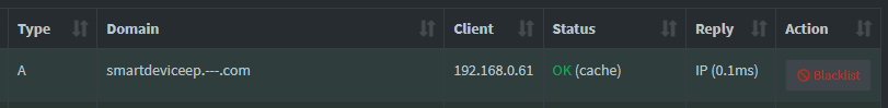
I use Pi-hole locally, which is a DNS server that blocks tracking and some ads, but it also has a useful feature to browse DNS queries by device. By navigating to the Tools > Network page and selecting the device's local network address, we can see it's querying the DNS server for the address of the cloud server's domain:
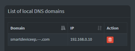
So now we know the cloud server's domain it's connecting to, we can use the Local DNS feature to send that network traffic to my local workstation (192.168.0.10) instead of their cloud server:
We can then use Wireshark to take a look at the traffic coming in from the smart device. We can do this by monitoring the workstation network interface with a filter of ip.addr == 192.168.0.61 (smart device address).
By doing this, I was able to see UDP packets being sent from the smart device to the workstation on the port 41014!
Packet Analysis
So, we know the smart device uses UDP to communicate with its cloud server. But right now, it's trying to communicate with my workstation and is expecting it to respond like its cloud server.
We can use a simple UDP proxy for our workstation to act as a relay between the smart device and its cloud server.
I used Cloudflare's DNS resolver (1.1.1.1) to look up the real IP address for their cloud server (because my Pi-hole DNS would have just resolved to my workstation's local IP address). Then I used node-udp-forwarder as a simple method to relay the traffic to their cloud server:
X.X.X.X being the real IP address of their cloud server.
Looking at Wireshark again, we can see all the network traffic between the smart device and its cloud server!
When booting the device, it would send a packet to the server with data like this:
The server would then respond with the following:
All of the packets after this seemed to share a similar structure. They did not include any readable strings but were full of what appeared to be random bytes of data; this could be the Avalanche effect pointing toward encryption.
I searched around to see if this packet structure was an existing protocol. I read that DTLS is used by some smart devices and that it is based on UDP.
However, Wireshark does support the detection of DTLS packets but listed this packet as UDP, which means it couldn't determine a UDP-based protocol from the data. I double-checked with the DTLS specification, but that described a header format different from what we see in the packet, so we know DTLS isn't used here.
At this point, we hit a blocker; we don't understand how the data is formatted in these packets, which means we can't manipulate or emulate anything yet.
This would have been a lot easier if it used a well-documented protocol, but where's the fun in that?
Physical Disassembly
We know there are 2 applications that understand how to read this packet data: the smart device and its cloud server. And well, I don't have their cloud server handy, so it's time to take a look inside the smart device!
It was quite easy to disassemble with a few easily accessible screws. Inside was the main PCB containing the microcontroller, a port connecting to the fan, and a ribbon cable to the control panel on the front.
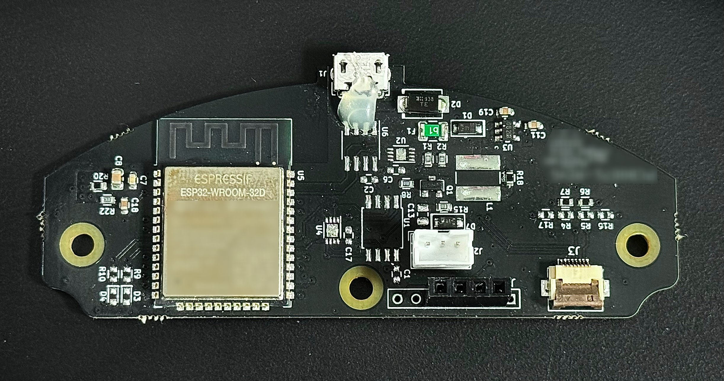
The main controller is labeled as an ESP32-WROOM-32D. This microcontroller is commonly used in smart devices and features WiFi and Bluetooth.
I stumbled across the ESP32-reversing GitHub repo, which contained a nice list of ESP32-related reverse engineering resources.
Serial Connection
The ESP32 contains a flash chip, which is where the firmware containing application logic is most likely stored.
The manufacturer of the ESP32 provides a utility called esptool to communicate with the ROM bootloader in the ESP32. With this tool, it's possible to read data from the flash, but first, we must establish a serial connection!
Referencing the ESP32 datasheet, we can find the pin layout diagram:

Here, we can see the TXD0(35) and RXD0(34) pins. We need to connect a wire to both of these pins and a ground pin for a serial connection.
The device PCB had a few pin holes, which are commonly connected to the pins for debugging and flashing; I was able to visually follow the traces from both of these serial pins to the holes! This allowed me to easily solder on breakout headers that I could temporarily plug jumper wires into. Otherwise, I would have likely carefully soldered directly to the chip pins.
With a multimeter set to continuity mode, I was able to locate which hole was ground by referencing the GND(38) pin on the ESP32.
Now, we need a port to handle this UART serial communication. I used my Flipper Zero, which has a handy USB-UART Bridge application under the GPIO category.
Using 3 jumper wires, I connected them together:
Flipper Zero TX <--> RX ESP32
Flipper Zero RX <--> TX ESP32
Flipper Zero GND <--> GND ESP32
The TX and RX wires are intentionally crossed here; we want to transmit data to the other device's receiving line!
In Windows Device Manager, under the Ports (COM & LPT) category, I found my Flipper Zero UART device as COM7. Using Putty configured to a Serial connection on COM7 at 115200 speed, I was able to successfully connect to the Flipper Zero. While searching around, I saw this speed was often used for the ESP32, so I decided to go with it here.
When booting up the smart device, I noticed a bunch of log data from the serial output:
We can pick out some useful information from this output:
The device has a 4MB flash chip.
The application runs from factory, which is a common partition name for the default application flashed at the factory.
A FAT filesystem is mounted.
The application reads files for:
Serial number
Device key
Two CA certificates (root and signer)
Server config
Dumping Flash
Awesome, now we have a working serial connection, we can focus on dumping the flash, hoping it contains information on how to read these packets!
To read the flash, we need to boot the ESP32 in a different mode, specifically what it calls the Download Boot mode. This is technically explained in the Strapping Pins section of the datasheet. But TL;DR, I held a jumper wire from a GND port on my Flipper Zero to the IO0(25) pin on the ESP32 while it boots.
Checking the serial output with Putty, we can see this successfully boots the smart device into the Download Boot mode:
Now we can close Putty and switch over to a Terminal to use esptool.
We're able to dump the entire 4MB of flash data from the ESP32 with the following command:
I dumped the flash a couple of times to ensure I had a good read and backed them up in case we accidentally brick something because then we can flash back the dump.
To read the flash successfully using the Flipper Zero, I had to change its config to specify the baud rate of 115200 instead of Host.
Flash Analysis
We have the ESP32 flash dumped into a single binary file, and now we need to make sense of it. I found esp32knife to be the best utility for this.
It reads the flash file and extracts a bunch of useful information. It was also the only utility that successfully reformatted this dump into ELF format with correctly mapped virtual memory, but more on that later! Let's see what we can find:
This logs out a lot of information and saves the output data to a ./parsed folder.
The first file of interest here is partitions.csv, this table maps areas of data in the flash:
Here, we can see a few interesting entries:
There are three application partitions. Two are labeled ota, which is where over-the-air firmware updates are written. The other is labeled factory, and we know from the serial output during boot this is the application partition that is currently used.
That storage partition has the FAT type, this like likely the FAT filesystem we saw mounting in the serial output.
nvs is a key-value storage partition, there may be some useful data here.
Other readers have mentioned that this flash dump could have been protected if the device had enabled flash encryption (which it does not in this case).
Device Storage
I was initially curious to see what data was in the nvs key-value storage partition.
The latest state of this data was extracted to part.0.nvs.cvs, and the only interesting data I could see was my WiFi SSID and password. But I also found the full historical changelog of values in part.0.nvs.txt and that revealed a couple of previously used WiFi credentials; what!? did someone use this thing before me?😆
Following that, it was time to look at the contents of the FAT storage partition. I found OSFMount to be a great Windows application for this; it mounts the filesystem image as a virtual disk and allows writing to it!
This revealed a few interesting files that we saw from the serial output earlier:
I inspected the contents of these files and found:
dev_info - a UUID labeled firmware, likely the version installed
dev_key.key - 256-bit private key (prime256v1), the public key for this was printed to the serial output labeled Device key!
serial - the serial number
server_config - the address and port number we found earlier
SmartDevice-root-ca.crt - a CA certificate with a 256-bit public key (prime256v1)
SmartDevice-signer-ca.crt - a CA certificate with a 256-bit public key (prime256v1) and the root certificate as its CA (certificate authority)
wifi_config - my WiFi SSID and password
The dev_key.key file started with -----BEGIN EC PRIVATE KEY----- which is an Elliptic Curve private key; I used openssl to verify this with:
And the two .crt files started with -----BEGIN CERTIFICATE----- which I also verified using openssl with:
Having the certificates and device key stored on the device strongly indicates they are used to encrypt the UDP network packet data.
Initial Static Analysis
Now we've taken a look at the storage, it's time to look at the application which runs on the device.
We know it's running the factory partition, so I opened the part.3.factory file in the Ghidra CodeBrowser. Ghidra is a free and open-source suite of reverse engineering tools from the NSA; it's an alternative to the paid IDA Pro.
This file we're opening is the partition image direct from the flash; it's comprised of multiple segments of data, each getting mapped to different virtual memory regions on the ESP32. For example, data at offset 0x17CC4 in the partition image is actually mapped to 0x40080ce0 in the device's virtual memory, so although this file contains all of the application logic and data, Ghidra won't understand how to resolve any absolute memory references, at least for now. There will be more on this later!
The ESP32 microprocessor uses the Xtensa instruction set, and Ghidra has recently added support for this! When loading the image, you can select the language Tensilica Xtensa 32-bit little-endian. We can run the auto analysis; although it won't give us great results just yet, we can still look at any defined strings it is able to find.
String Theory
Text strings in a compiled application are a fast-track way of locating and understanding logic when reverse engineering; they can reveal a lot about the application.
Because this compiled file only contains bytecode instructions for the processor, there are no function names, data types, or parameters. It can initially seem like a giant blob of nonsense, but as soon as you a string reference like Failed to read wifi config file, you can start to piece together what the logic is doing. Reverse engineering compiled applications can be difficult, but it is certainly a rewarding challenge.
So, I had a look through the Defined Strings window in Ghidra to see what I could find, and noticed all of the strings we saw in the serial output, such as:
As expected, the address is the string's location in the partition image. Ideally, this should be the address in the virtual memory when running on the ESP32; that way, we can see any bytecode that references this string. We'll tackle that soon!
In close proximity to these strings were some others of interest:
There is so much useful information that we can extract from these strings. Even without reading the assembly, we can start to assume what it's doing with the data.
Here's what I noticed:
CRC error code: this is a checksum algorithm that could be part of the packet data.
mbedtls is an open-source library implementing cryptographic primitives, X509 certificate manipulation, and SSL/TLS and DTLS protocols.
ECDH and HKDF primitive functions are used directly from mbedtls. We already know it's not using the DTLS protocol, so we can assume it's using them to implement a custom protocol.
We can also assume the files mentioned nearby are also related:
Serial number
Device key
Root certificate
Signer certificate
An "ECC conn packet" is sent from the client; this is part of the ECDH key exchange process; we'll also get to that later!
Ghidra Setup
Ok, it's about time we configure Ghidra to analyze this ESP32 application better.
First up, esp32knife supports reformatting the binary partition image for the application into an ELF format, which Ghidra can better understand. I had to make a small tweak for it to support the RTC_DATA segment, which I've pushed to my fork on GitHub: feat: add support for RTC_DATA image segment.
We can then import the more useful part.3.factory.elf instead of the part.3.factory binary partition image.
But when importing this time, we want to do a couple of things before running the auto analysis, so let's opt out of doing that for now.
Next, we can use the SVD-Loader-Ghidra script to import the peripheral structs and memory maps from the official esp32.svd file.
We can also use the built-in SymbolImportScript script to load labels for all ROM functions. I've published a file with all ROM function labels for the ESP32 ready for Ghidra here: ESP32_ROM_LABELS.txt. This will help us identify common ROM functions like printf.
Finally, we run the auto-analysis from the menu bar Analysis > Auto Analyze.
Let's see what that does to the strings we found earlier:
We can now see the same strings are mapped correctly to their virtual memory addresses, meaning the analysis will detect any pointers or instructions that reference them!
There are multiple versions of the ESP32, such as ESP32c2, and ESP32s2. The ROM labels and .svd file I've linked are for the default ESP32. if you have a different version, you'll need to import the specific .svd and create specific ROM labels following the README in my gist.
Firmware Modification
Up until this point, I have the PCB awkwardly positioned to keep the fan and control panel connected. So, I wanted to see if it would still function with them unplugged. Unfortunately, it did not; the serial logged the following:
Now we have Ghidra configured nicely, I took a look at the address mentioned in the log; it was assembly right next to a reference for the No Cap device found! string, and at the start of the function, it logs "CapSense Init\r". This must be for the control panel that uses capacitive sensing input!
I named this function in Ghidra to InitCapSense:
I then followed the references to this function back to another function that appeared to be starting as a task/service; I renamed this one StartCapSenseService:
Again, I followed the function references and found the function that calls StartCapSenseService. Using Ghidra's Patch Instruction feature, I replaced the call instruction with a nop (no operation) instruction to remove the function call:
We want to flash this change to the ESP32, so I replaced the bytes that were modified, not in this ELF file, but in the part.3.factory binary partition image, because that is in a raw format directly from the flash, so it will be easy to write back. I use a hex editor to find & replace the bytes:
2564af 653100 e53700 -> 2563af f02000 e53700
Then, I wrote this modified image to the ESP32 flash at the offset 0x10000, that is the offset from the partition table for the factory partition:
But when trying to boot this, we get an error from the serial output:
Alright, so there is a checksum. Luckily, the code inside esptool knows how to calculate this, so I threw together a quick little script to fix the checksums for an application partition image: feat: add image checksum repair script.
Now, we can use this to repair the checksums and flash the repaired image:
I tried booting the device without the control panel again; everything now works ok! We have successfully just modified the smart device's firmware!
Packet Header
Let's get back to focusing on the packets. We know the packets do not follow a well-known protocol, meaning we must figure out the structure ourselves.
I captured the packets from the device booting numerous times and compared them to each other. I noticed the first thirteen bytes were similar to other packets, while the rest of the packet seemed to be encrypted.
Here's the first packet received from the server between boots; you can see the data matches up until the offset 0x0D:
It wasn't too difficult to figure out the first couple of values, then I noticed the remaining nine bytes matched the serial number from the device's serial output, and there we have the packet header format:
A magic byte is commonly used to identify a piece of data in a specific format uniquely.
A size-related byte and message ID are very common to expect in a packet like this.
The packets first sent and received had a slightly different format to those that followed; there were always the bytes 00 01 after the header in the client packet, and it was the only packet with the message ID of 0x02.
Comparing it to the other packets, I noticed a pattern with the message ID:
0x02 - First packet sent from smart device
0x82 - First packet received from cloud server
0x01 - All other packets sent from smart device
0x81 - All other packets received from cloud server
You can see the higher bits in this value represent if it's a client request (0x00) or a server response (0x80). And the lower bits are different between the first exchange (0x02) and all other packets (0x01).
Packet Checksum
We noticed a string in the application earlier that said "Message CRC error\r" which implied there is a CRC checksum in the packet. It would be helpful to know if there is a checksum in the data so it doesn't interfere with any decryption attempts.
I followed the references to this string, and a single function references it.
Let's take a look at the Decompiled code for that function:
We can see the s_Message_CRC_error label being used in the else block, so the if statement must verify the CRC data for a message.
This logic compares the results of 2 functions FUN_4014b384 and FUN_400ddfc0. If this is verifying the checksum of a packet, one must generate a checksum for the packet data, and the other must read the checksum value from the packet.
We could use the arguments to help us decide which is which, but let's take a look at both:
This doesn't look like a CRC function. It actually looks like a function that reads a 16-bit uint with configurable endianness; here's why:
Multiplying a value by 0x100 (256) is the equivalent of shifting left by 8 bits (half of a 16-bit value), so 0x37 becomes 0x3700. The logic in the first if code block adds this to the byte at index[1]; this is the next byte after it in memory, so that's basically reading a big-endian uint16 from the param_2 pointer
The logic of the else code block is similar but shifts the second byte instead of the first, thus reading a little-endian uint16. So, the param_1 parameter configures the endianness of the result.
The return statement does a bitwise AND (&) operator on the return value with 0xFFFF, this restricts the value to 16 bits of data by zeroing out any higher bits.
Now, this looks a lot more like a checksum function; there's a for loop with a bunch of bitwise operators inside.
I open up one of the captured packets into ImHex, a hex editor for reverse engineers. This has a handy feature to show the checksum of the currently selected data.
Because the other function reads a 16-bit uint, I select CRC-16 and start selecting regions of bytes that would likely be hashed, leaving 2 bytes unselected where I think the 16-bit hash could be.
No luck so far, but then I noticed you can configure the CRC-16 parameters in ImHex. So, I tried a cheap shortcut and set up ImHex to calculate CRC-16 checksums with a bunch of different parameter combinations using the values found in the decompiled function.
Success! The last 2 bytes of the packet turned out to be a CRC checksum of all other data in the packet, specifically CRC-16 with 0x1021 polynomial and 0xFFFF initial value. I checked this with other packets, and they all passed the checksum.
Now we know the last 2 bytes of every packet are a CRC-16 checksum and can exclude it from any decryption attempts!
Key Exchange
Earlier, we noticed mbedtls primitives labeled as ECDH and HKDF. So, what exactly are they?
ECDH (Elliptic Curve Diffie–Hellman Key Exchange) is a key agreement protocol that allows 2 parties (like the smart device and its cloud server), each having an elliptic-curve public–private key pair, to establish a shared secret over an insecure channel (UDP). I found a great explanation of this in more detail in "Practical Cryptography for Developers": ECDH Key Exchange.
Essentially, if the smart device and server generate an EC key pair and exchange their public keys, they can use the other's public key with their private key to compute a shared secret key. This shared secret key could be used to encrypt and decrypt the packets! And even though they exchange public keys over the insecure network, you still need one of the private keys in order to compute the shared key.
This is ideal for securing packets like this, and the first packet sent by the client is actually named the ECC conn packet in the logs:
This is great progress; we know the first packet exchange is likely exchanging EC public keys to establish an ECDH key agreement to encrypt all the other packets.
If we ignore the packet header (13 bytes from the start) and checksum (2 bytes at the end), we can see the contents of the packets for this potential key exchange are both 32 bytes (256 bits), which would be a valid size for a public key. Even though the client's request has 00 01 at the start, we can assume this is some unimportant data descriptor as it doesn't change value between boots:
Ok, so what is the HKDF? That is HMAC-based key derivation. It can be used to convert shared secrets computed from Diffie–Hellman into key material suitable for use in encryption. Wow, that makes a lot of sense; it's most likely doing exactly that to derive a key to encrypt and decrypt the other packets.
Cryptography Analysis
To be able to decrypt these packets, we need to understand exactly how the key for encryption is generated. That includes any possible input data as well as configurable options.
It's safe to assume the ECDH and HKDF functions are used for the packet data, so focusing on the key generation process, I summarize the variables we need to understand:
ECDH:
Public key
Private key
HKDF
Hashing method
Output key size
Optional salt
Optional info
The smart device and its cloud server both exchange 256 bits of data during what we assume is the key exchange process. But remember, the smart device firmware also loads the following keys from storage:
256-bit device key pair (private & public)
256-bit cloud server "root" public key
256-bit cloud server "signer" public key
There are a lot of possibilities here, so I take another look at the application in Ghidra. By following the error strings, I located the function which generates this key! I steadily work my way through labeling functions and variables by comparing the assembly to the mbedtls source code. I was able to annotate and simplify it to the following pseudocode:
Being able to interpret assembly or even the decompiled code in Ghidra is certainly an acquired skill; I'd like to emphasize this took a while to figure out, with many breaks in between!
This function does something unusual; here's what we can learn from it:
The generated ECDH key pair is discarded and replaced by keys loaded from somewhere else in memory, which is strange. Because the ECDH key pair generation function isn't used elsewhere in the application, it's likely these keys are the files from the firmware storage we saw earlier.
The algorithm used for the HKDF is SHA-256.
The computed shared secret is used as the HKDF salt.
Random bytes are generated as the HKDF input.
The device serial number is used as the HKDF info.
The HKDF output key size is 0x10 (16 bytes / 128 bits).
We now have a much better understanding of how the smart device generates the potential encryption key.
It's useful to keep in mind that their cloud server also has to generate this key, meaning it needs to have all the same input variables to the HKDF.
Knowing this, we can recap the three dynamic inputs to the HKDF function and understand how the server will also have them:
salt - Shared secret: The server must have access to the same private and public keys used for the ECDH shared secret computation or use the public to our private and the private to our public.
input - Random bytes: The server must have access to these randomly generated bytes on the smart device; either we send these bytes to the server, or technically, the server could recreate the pseudo RNG method used. However, the generated bytes have the size of 0x20 (32 bytes / 256 bits) which exactly matches the size of the data sent in the key exchange packet, so it's highly likely we're sending it there!
info - Device serial number: We already know the device serial number is part of the packet header, so the server easily has access to this value.
Curious to know what the application did with these randomly generated bytes, I checked what the calling function did with them:
We can see the random bytes from GenerateNetworkKey are written out to the stack, and better yet, the 00 01 bytes are written to the stack just before it, and then all 0x22 bytes are sent in the packet. That exactly matches the format we saw in the key exchange packet!
Logging Key Data
Much progress has been made via static analysis, and the final value we need to calculate the decryption key is the shared secret.
At this point of reverse engineering, I hadn't reversed the functions as cleanly as shown in this blog post and wanted to try to dynamically obtain keys directly from the device.
Debugging via JTAG would be the sensible choice here. However, I didn't notice breakout points for these pins on the PCB, and I wanted to avoid soldering directly to the ESP32 pins, so I thought I'd challenge myself to patch the firmware to print it over serial!
The CapSense service is still disabled, so I thought I'd write a function over that logic to print out the shared secret key and call it right after it was computed!
So, planning in pseudocode, I'd want to add my function call to the GenerateNetworkKey function. Right after it has generated the key.:
While referring to the Xtensa instruction set architecture manual, I threw together some assembly like this:
We patch over the GetDeviceSerialNumber function call because this is directly after the generation of the shared secret key, and the pointer to the key is still in the register a2.
I flashed the modified firmware, booted up the device, and checked the serial output:
Success! We've printed out the shared secret key!
I rebooted the device numerous times to see if the key changed, and it remained the same. It is most likely computed using the keys in the firmware storage, but now we have the computed static value, we don't need to reverse the computation process.
Packet Decryption
Alright, we now understand the method to derive the decryption key and have all input values; it looks something like this:
To be on the safe side, I wrote another firmware patch to print the key output from the HKDF call and tried recreating the key from captured packets. It works! That confirms we have correctly reverse-engineered the key creation function and are able to replicate the key creation logic in our own application.
But now we need to find which encryption algorithm is used. I refer back to the function which formats packets and found the call to the encryption function:
I noticed that after the device serial number is copied to the packet, 16 random bytes are generated and copied directly after it. These bytes are also provided to the encryption function. So, we know they are an input variable to the encryption algorithm.
We know the key is 128 bits, with another 128 bits of additional random data.
I looked into the encryption function, which is very clearly crypto-related due to the looping of a bunch of bitwise operations, and noticed a reference to a static block of data.
This data started with 63 7C 77 7B F2 6B 6F C5, a search in the mbedtls source code revealed it is the AES Forward S-Box!
I decided to jump straight into attempting AES decryption on the captured packets and successfully decrypted a packet!! 🎉
The algorithm was AES-128-CBC and the additional random data was used as the IV (Initialization vector).
MITM Attack
We can now create an MITM (man in the middle) attack that does not require any firmware patching. This is because the private key of the device is now known, the key derivation logic has been reverse-engineered, and any required dynamic data is exposed over the insecure network.
If it correctly implemented ECDH, the smart device would have a unique private key that isn't exposed, and our easiest route of attack would be to generate our own server key pair and do any firmware modifications so the device accepts our custom public key.
But because of their custom protocol's design, we can write an MITM script that can intercept, decrypt, and potentially modify network communications without any modifications to the smart device. So, that's what we're going to do!
The main aim now is to decrypt and log as much data as possible; then, we can reference that to write a local server endpoint that entirely replaces their cloud server.
I hack together a quick Node.js script to do this:
Here, we combine all of our research to implement an MITM attack.
Just like when we first captured packets, we configure Node.js to use Cloudflare's DNS resolver to bypass our local DNS server.
We create a UDP socket locally to accept packets from the smart device and also a socket to communicate with the cloud server.
Anything we receive from the smart device, we log and send to the cloud server
Anything we receive from the cloud server, we log and send to the smart device
We treat packets with the messageId of 2 to be the key exchange packet where the smart device send the random bytes to the server, we then calculate the AES key used to decrypt future packets.
While capturing, I used their mobile app to remotely control the smart device so we could reference the logs and replicate the logic ourselves.
Data Exchange Format
We now have the decrypted packet data, but the data is still in a serialized binary format:
My mind was deep in the world of reverse engineering, and I managed to reverse the structure for all packets and hack together some JavaScript to convert the data to and from JSON.
The header was quite simple, again just some IDs and length, but in little endianness:
01 00 - packet ID
64 00 - transaction ID
29 00 - serialized data length
And with some tinkering, I figured out the serialized format:
82 - Map
A4 - String of 4 length
A7 - String of 7 length
This was fun to reverse because the typing was more described in bits, but it's clearly readable from the bytes for these simple cases.
Looking back on this, I'm not sure why I didn't look for an existing solution that matches this serialized binary data format; I was expecting everything to be a custom solution at this point. But having a search now, this is just MessagePack, so I guess I just reverse-engineered and wrote a partial msgpack implementation 😆
Switching over to a popular implementation, we can see the data is easily unpacked into JSON:
Network Log Analysis
In preparation for writing a custom local server for the smart device, let's take a look at the unpacked network logs we've captured:
🔑 Key Exchange Packet:
The smart device sends random bytes to the server to be used in the HKDF.
↙️ Get Device State:
The smart device fetches its initial state from the server when it boots.
🔗 On Connect:
When the smart device connects to the server, it sends its current firmware UUID. The server responds with the potential UUID for a firmware or config update that could be downloaded.
⤵️ Server Updates Smart Device State:
When the server wants to update the smart device's state, it will send a packet like this.
⤴️ Smart Device Updates Server State:
The smart device sends its latest state to the server whenever it changes.
🛜 Keep Alive:
The smart device frequently sends a keep-alive packet to the server so the server can potentially use the open connection to send state updates.
MQTT Bridge
We're going to need a way to connect Home Assistant to our custom server, which handles the smart device networking. MQTT is ideal for this; it's a protocol designed for IoT messaging and can be easily configured within Home Assistant. For this, I set up the Mosquitto addon for Home Assistant, an open-source MQTT broker that connects everything together.
The connection chain will look like this:
Home Assistant <--> MQTT Broker <--> Custom Server <--> Smart Device.
The custom server logic in pseudocode would look something like this:
This logic seems quite minimal but is carefully designed. The latest state is retained in the MQTT broker. However, the source of truth for state updates is always the device, meaning the state will never update in the MQTT broker unless the device updates it via the custom server. This covers a couple of edge cases:
If the state update was unsuccessful, we should not display the state as updated.
The state update should be reflected via the MQTT broker if the smart device was updated via its physical control panel.
The three main cases we are supporting here are:
When the smart device boots and initially connects to the custom server, it requests the latest state; we can attempt to obtain this from the MQTT broker's retained value or fall back to a default state.
When Home Assistant wants to update the state, it will send a command to the MQTT broker. We can subscribe to this command topic from the custom server and forward the request to the smart device.
When the smart device's state changes for any reason, it sends the mirror_data packet to update the server state; we send this value to the MQTT broker to update the state and tell it to retain the data as the latest value.
I run this custom server alongside Mosquitto and Home Assistant on my small home automation server. Then configured my Pi-hole local DNS to resolve the cloud server's domain to my custom server.
Home Assistant Integration
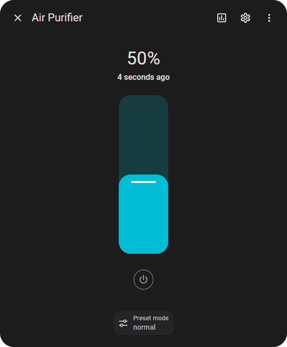
The final step in this process is configuring Home Assistant to map the MQTT topics to a device type. For my air purifier, the closest integration was an MQTT Fan; in my configuration.yaml I added something like this:
I added topics to control the fan speed and turn the device on and off.
Everything works! I've been running this for a couple of weeks now, and it has worked fine without any issues! I've even set up a little automation, so if my separate air monitor's PM2.5 or VOC level gets too high, it boosts the air purifier for a while!
Technical Recap
For better or worse, the engineers behind the service decided not to implement a standard protocol like DTLS. They created a custom solution which introduced some downsides to the system:
We're not certain if each device has its own unique private key, but whether it does or not, both have downsides:
If all devices share the same firmware private key, the attacker needs to reverse engineer just a single device to MITM attack any other devices.
However, if every device has its own unique private key, the server must keep a data store mapping device serial numbers to the key of each device. So, In the case of any data loss, the server would entirely lose the ability to respond to any device communications; that is a scary thought for the business. Unless there is an insecure network fallback in place, which is equally alarming and time-consuming to develop
Because the firmware contains a private key that is static, an attacker needs a single firmware dump to obtain the key and perform an MITM attack. Whereas, if an EC private key was instead generated at runtime, write access would be required in order to patch the server public key or application firmware, which could be protected by other means.
Also, the mobile app has a 1-star review on the app store. It makes me wonder if there is a correlation between the unexpectedly custom technical implementation and the abnormally poor end-user app experience. Building a custom system is far more than just the initial development; systems need support, and bugs need fixing.
Overall, it wasn't a bad implementation from a security perspective; you'd still need physical access to attack the device; there are pros and cons to everything and variables that aren't visible from our perspective.
The custom implementation increased the obscurity of network communication. However, Security through obscurity is simply a short-term win. While it may deter generic attacks on standard technical implementations. In the bigger picture, it's just an annoying yet passable hoop for an attacker to jump through.
I've had a few conversations recently about why engineers build from the ground up vs. using proven standards. And that's a very interesting topic; I'll save that for another post!
Conclusion
What a crazy journey that was!
I'd like to emphasize that the reverse-engineering process was not as smooth as it may seem from this post; I've done my best to format everything to be best read by you. But in reality, I was often in the dark, unsure if the next thing would work or not, and juggling many tasks and theories, iteratively making progress in multiple places to test my assumptions ASAP.
I tried some things that hit dead-ends and weren't worth dedicated sections in this post:
I tried running the firmware in Espressif's fork of QEMU, patched out the CapSense service, and loaded virtual e-fuses to match the MAC address from the firmware, all to find out it doesn't support WiFi emulation. It was fun to see it booting virtually, though!
I also tried flashing a different serial number, device key, and certificates to see if that affected anything before I got around to fully reversing the application logic. I didn't get much from this. Turns out this likely would have just affected the computed shared secret used for the HKDF salt, which we dumped anyway.
I've certainly sharpened a variety of skills from this project. I'm also proud I achieved my goal of adding this device to Home Assistant! The moment I managed to successfully decrypt the first packet was great; everything just clicked into place.
I'm still curious to explore creating an open-source project to de-cloud and debug smart home products; I've learned much more about the technical aspects of achieving that.
Thanks for reading! I hope you found some value in this post. I put a massive amount of effort into creating it, probably more than I did actually doing the project itself. It would be amazing to receive feedback on the format!
I'd also really appreciate it if you could help share the post.
You can drop a follow on X to stay updated with what I'm doing.
If you found it helpful and would like to support my content creation, you can Buy Me a Coffee! Your support helps me continue creating content and sharing my passion for reverse engineering!
Take it easy 👋


 English (US) ·